The first stage when a finite element calculation is made, consists of the obtaining the mesh, or the spatial description of the different parts of the model by meshing of its geometry from its defining CAD. This job can be achieved using different types of elements of 3, 2 or 1 dimensions, as solid elements (4 to 8 nodes), plates or shells and membranes (3 or 4 node elements), beam, bars, spring/dashpot and joint elements.
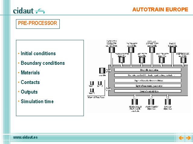
The pre-processor reads mesh files written under various standard formats ( I-DEAS™ universal file, PATRAN™ neutral file and NASTRAN™ input file, ...), and generates a file that can be used as input in the executable solver.
As soon as the mesh has been imported, the pre-processor allows all the information necessary for the solver to be generated, model data, initial conditions, boundary conditions, materials, contacts, outputs, simulation time ... and checking the model (time-step display on the mesh, mass, inertia, geometric element quality...). It also enables the merging of several mesh files into a single model and performing basic mesh modifications (mesh renumbering, welding of nodes, ...), modification and creation of parts by geometrical transformation (translation, rotation, symmetry,...), surface reorientation, ...
Once the required information of the model and the demanded outputs are introduced, the calculation is run by means of the main program execution, whose input is the file obtained from the pre-processor.