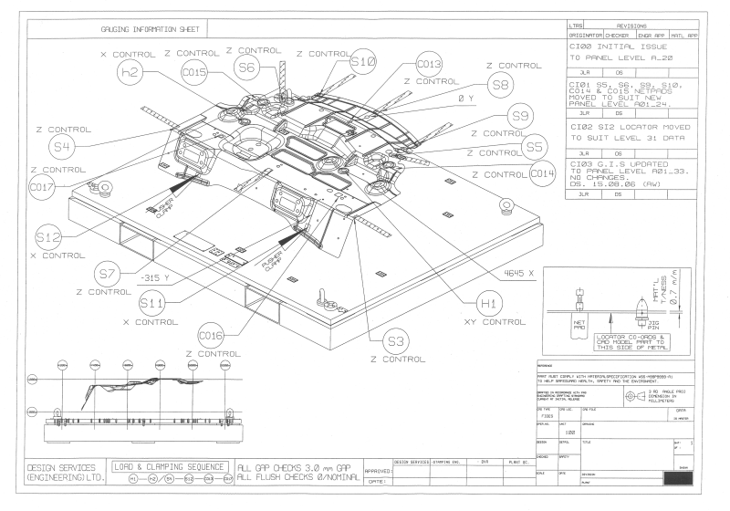
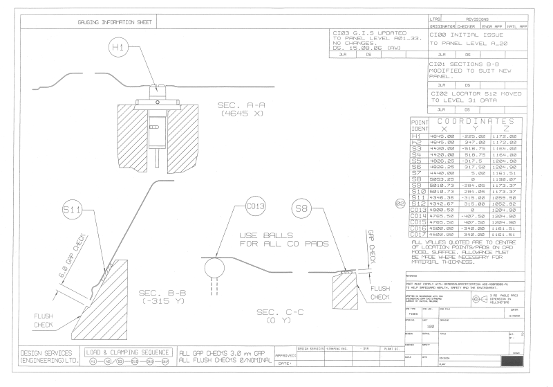
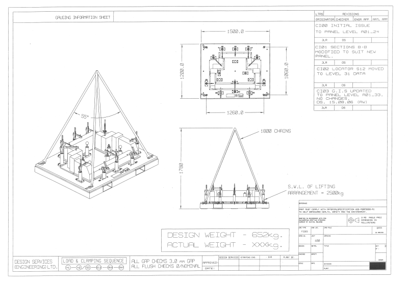
Concept designs for the proposed fixturing should be developed and presented by the gauge maker early on in the design stage in the form of a Gauge Information Sheet (GIS). This will ensure that the customer is happy with the direction of the work and is also an opportunity for any issues arising or not covered in the specification to be identified and addressed. The concept design would be expected to include details of part orientation to base plate, clamp type and sequence, locator pins and measurement points.
The Gauging Information Sheet should include the following:
- A three dimensional technical illustration of the component in question, clearly showing positions of locators and clamps, and the orientation of the component with respect to the fixture base.
- Type and geometry of locator pins, clamps and net pads to be used, and the loading and clamping sequence.
- The x, y, z co-ordinates of all locator pins and net pads, and any other significant feature(s), and an explanation of where these measurements are taken to (centre or edge of pad etc.)
- Details of the fixture specification and necessary equipment for the safe lifting and transporting of the fixture, including total weight, position of lifting points and chain length (if relevant).
 |
Click the picture thumbnails on the left for enlargements.
Page 14 out of 18


