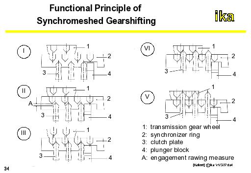
The picture indicates the sequence of events that take place during synchronized gearshifting.
Point I:
As a result of the gearshifting force, the clutch plate (3) along with the plunger block (4) moves out of the neutral position in the direction of the gear that has to be engaged. The gearshift play amounts to zero.
Point II:
The synchronizer ring and the gear wheel are loaded by the plunger blocks and the synchronizer spring (pre-synchronization).
The cone clutch goes into operation. This leads to the synchronizer ring (2) moving into the initial locking position. The engagement measure (A) is run through. So far no significant gearshift force can be measured.
Point III:
After having run through the engagement measure, the roof slants of synchronizer-ring and the interlocking clutch (sliding sleeve) come into contact with each other and the gearshift force increases quickly. The main synchronization starts off.
As a result of the gearshift force, the following torques develop at the synchronizer elements:
The synchronizing torque between gear wheel cone and synchronizer ring,
The plunger moment between the roof slants of synchronizer ring and sliding sleeve,
The supporting torque between synchronizer ring and plunger block.
During the main synchronization, the synchronizing torque is larger than the plunger torque. Early shifting through is prevented. During this phase, there is no axial displacement of the clutch ring.
Point IV:
When the synchronizing speed is achieved, meaning that the clutch ring (3) and the gear wheel (1) are at te same speed, the clutch ring can rotate relative to the synchronizer ring (2) at the roof slants. The teeth of the clutch ring can now pass through the the synchronizer ring.
Point V:
In the last phase, a positively-engaged connection with the synchronized gear is obtained.
The gearshift is terminated by closing the main clutch.