2.4 Four-Wheel Vehicle Model
In addition to basic investigations about the stability behavior of the control system vehicle, the single-track vehicle model dealt with so far, already permitted a qualitative study of the influences of some vehicle parameters, e.g., the effect of the location of the center of gravity or of different front or rear cornering stiffness (side slip stiffness) on understeer and oversteer.
The driving stability of real motor vehicles is determined by a multitude of further parameters, with the height of the center-of-gravity, anti-roll suspension rates and wheel suspension kinematics constituting major factors of influence. When the stability limit with respect to driving dynamics is approached, the lateral dynamic response of a vehicle will increasingly be influenced by the drive concept.
Investigations about the dependence of steering behavior and driving stability on these parameters require replacement of the linearized single-track vehicle model by a three-dimensional four-wheel vehicle model, which above all also includes a more precise representation of the nonlinear tire characteristics. 2.4.1 Model Formulation
Section 2.3. contains the linearized equations of motion for the single-track vehicle model and an analysis of the influence of the vehicle parameters on steering behavior and course stability on the basis of these equations. The system of equations describing the motion of a three-dimensional four-wheel vehicle model cannot be analyzed due to its complexity. Hence, for the following parametric study, the simulation model of a complete vehicle is generated using ADAMS.
In order to create a vehicle computer model, the individual components of the vehicle have to be described at first. The ADAMS database consists of each part being characterized by its mass, the coordinates of its center of gravity and its moments of inertia around the three primary inertia axes. Points are indicated on each component, where various parts are to be linked by joints along with the forces acting on them.
The various types of joints are available in a "library", with the number of the degrees of freedom being stated for each joint.
A similar procedure is used for forces. From a list of linear forces, for example, general spring-and-damper elements or compression-only forces can be selected for the modeling of stoppers or collision points.
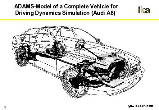
By means of self-written FORTRAN subroutines, random nonlinearities can be included in the calculation, in addition to the standard elements for forces and motion. Hence, for example, tire characteristics can be fully described by means of measured maps (cf. Section 2.2.4.1). Fig. 2.4-1 shows the ADAMS model of a complete vehicle.