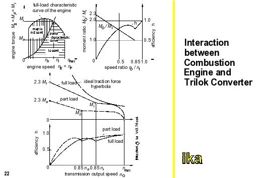
The interaction between trilok converter and the combustion engine proceeds as follows:
Up to the coupling point, the flow ratios at the pump wheel input are independent of the ones at the transmission output because of the stator, which is at a standstill. The important k-factor and thus the pump characteristic curve are constant. In this case, the pump characteristic curve, if possible, should be located within the area of optimum engine efficiency. Above the coupling point, when stator- and turbine wheel rotate as a "common" turbine wheel, the same principles as in the hydrodynamic clutch are applicable. There, the pump characteristic curve moves dependent on the speed ratio nA/nE. We can see from the figure, that only a part of the engine map can be used in this way. Through the interaction of the engine torque and trilok converter characteristic, the output torque which is indicated in the figure finally results.
Compared with the ideal torque curve, there are still relatively large differences between the torque demand and torque supply. This means that the attainable conversion area (starting conversion approx. 2.0-2.5) and the poor efficiency at high torque ratios are not sufficient for the exclusive employment as a torque converter in the motor vehicle. Trilok converters are thus combined with stepped transmissions to form automatic transmissions. Apart from the favourable approach towards the demand characteristic curve achievable here, the advantages of the trilok converter become obvious only in this combination. The advantages include compactness, good heat dissipation over the hydraulic fluid, the fact that it is largely free of wear, and also in its function as a torsional vibration damper.