Hydrodynamic Transmissions
In hydrodynamic transmissions, torque transmission takes place according to the Föttinger principle using two rotating turbine blade wheels, the pump and the turbine wheel. In contrast to hydrodynamic clutches, in addition the hydrodynamic transmission includes a stator as moment support that props up at the housing.
As a result:
MT = MP + MS Eq. 3-51
where: MT = turbine wheel moment
MP = pump wheel moment
MS = stator moment
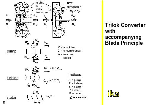
The figure shows the constructional details of a hydrodynamic transmission (Trilok converter) which is almost exclusively used today, with accompanying blade principle and flow conditions for nA/nE = 0.7.
The working fluid, which is generally oil, is accelerated by the pump wheel linked to the engine, transferred to the turbine wheel where it is slowed down. While doing so, it gives away its energy to the transmission output. An additional redirection more or less without delay leads to torque reinforcement. This reinforcement is the higher, the larger the speed difference is between pump and turbine. With v = 0, implying a firmly braked turbine, the torque conversion reaches its maximum value. With an increasing turbine speed, torque conversion drops almost linearly up to the torque ratio 1:1 (coupling point).
In the present example, at the indicated speed ratio, an optimal point of operation appears at approx. nA/nE = 0.7 without impact loss. If the speed ratio increases further, the stator is increasingly streamed from behind until at a speed ratio at approx. nA/nE = 0.9 (coupling point), the stator does not produce a deflection anymore, meaning that it does not absorb a reaction moment. In order to avoid this torque deterioration at a further increased speed ratio, the stator is connected with the transmission housing by a one-way clutch so that it can run along without moment transmission at speed ratios above the coupling point. In this area, the trilok converter works as a clutch.