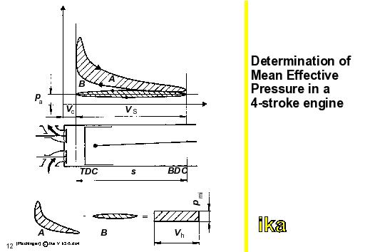
In the pi-V-diagram, the positive work performed on the piston corresponds to the clockwise area enclosed (compression and expansion). An area enclosed counterclockwise indicates negative work (intake and exhaust). In the case of the 4-stroke system (shown in figure), the internal work done per working stroke is obtained by computing and subtracting both enclosed areas. When the resulting area is replaced by a rectangle equal in area with the cylinder displacement VH as a basis, the height of the rectangle corresponds to the indicated mean effective pressure pmi.
Pi=pmi·AKo·sKo·i·nmot·z
where: pmi=mean effective pressure
Ako=piston area
sKo=piston stroke
i=working strokes per crankshaft revolution (i=0.5 for 4-stroke, i=1 for 2-stroke)
nmot=engine speed
z=number of cylinders
The effective power Pe at the shaft is smaller by the frictional power Pr caused by internal losses. The ratio of effective to indicated engine power defines the mechanical efficiency
Through the effective power measured at the flywheel, the mean effective pressure pme is determined analogous to pmi. The mean effective pressure is proportional to the engine torque Meng.
In the spark ignition engine, the indicated mean effective pressure pmi mostly depends on the volumetric efficiency of the cylinders. By increasing the vacuum during intake, the cylinder charge improves as speed goes up in the lower speed range. At high engine speeds, the volumetric efficiency drops as a result of increasing flow losses in the inlet and exhaust channels.
At the same time mechanical losses increase with engine speed. This results in a peak for the mean effective pressure pme and thus for the engine torque Mmot being achieved in the mid-speed range. In contrast, the peak effective power is reached at a higher speed, the so-called nominal speed. Below a minimum speed, the engine does not produce torque.