Characteristic of the Injected Disturbances

Frequency : 5kHz for Voltages < 4kV, 2.5kHz for Voltages > 4kV
Amplitude Level
| Level |
Max Level for Output test voltage (in open circuit, peak, kV) |
| Access to power posts |
Other Access |
| 1 | 0.5 | 0.25 |
| 2 | 1 | 0.5 |
| 3 | 2 | 1 |
| 4 | 4 | 2 |
| X | Special | Special |
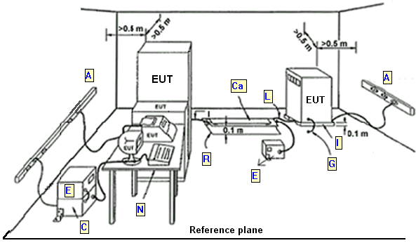
General test set-up for laboratory type tests
The disturbances are applied for minute at least, with a positive polarity and then negative by a required level. The
tested apparatus must continue to work normally.

Caption index :
A : AC mains supply
C : Coupling/Decoupling network (A). (A)=location for supply line coupling.
Ca : Capacitive coupling
E : EFT/B Generator (B). (B)=location for signal lines coupling.
G : Grounding connection according to the manufacturer's specification. Length to be specified in the test plan.
I : Insulating support
L : l=length between clamp and EUT to be tested, should not be more than 1m.
N : Non-metallic table
R : Reference plane
| 
